
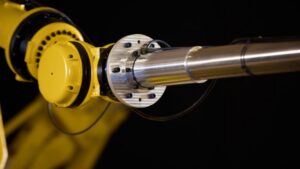
High-Performance Stepped Tube Structures: Optimizing Deflection, Weight, and Damping in Industrial Applications
Introduction & Industry Challenge
In robotics, packaging, and automated machinery, structural design constantly battles the trade-off between stiffness, mass, and dynamic settling time. Standard industrial metal tubing—typically homogenous steel or aluminum—is limited by uniform cross-sections. While stepped or tapered profiles are mathematically more efficient for minimizing cantilever deflection, creating them with off-the-shelf metal tubing requires expensive custom machining, heavy reducers, or bolt-on couplings that introduce point-loading and add parasitic mass.
Furthermore, minimizing mass at the end-of-arm tooling (EOAT) is critical. Excess mass at the end of an extended link exponentially increases the mass moment of inertia, driving up torque requirements on robot joints and severely limiting allowable payloads.
The Techreo Innovation
Techreo has developed a proprietary composite manufacturing process that enables high-strength, telescoping, and stepped tubular structures with custom, precision-matched slip fits. This eliminates the need for external couplers or secondary machining, delivering structures that achieve up to a 50% weight reduction compared to aluminum while maintaining equivalent structural stiffness.
[ Region 1: Roll-Wrapped Carbon Fiber Inner Mandrel ]
↓
======================================================= (Bond Layer)
[ Region 2: Helically Wound Metal Foil Matrix ]
======================================================= (Bond Layer)
↓
[ Region 3: COTS Commercial Aluminum Outer Shell ]
The architecture consists of three distinct, co-axial material regions:
- Inner Region (Precision Carbon Fiber Core): A roll-wrapped carbon fiber tube formed on a custom mandrel. The number of composite plies is tailored to meet specific directional wall-thickness and stiffness targets. The outer diameter (OD) is centerless-ground to provide an optimized surface energy and tight tolerance for adhesive bonding.
- Middle Region (Wound Foil Matrix): Thin metal foil is helically wound directly onto the carbon fiber core. A uniform layer of high-performance structural adhesive is applied to the foil during winding. This bonds the foil to the core and integrates the adjacent foil layers, building a precise intermediate wall thickness.
- Outer Region (Commercial Protective Shell): The assembly is thermally cured under consolidation pressure to ensure concentricity and a smooth profile. It is then coated with an engineered structural adhesive layer (typically maintaining a 0.015″ radial clearance) and press-fit into a commercial-grade outer tube (e.g., aluminum).
Interlocking Flexibility & Joint Mechanics
Because the axial lengths, wall thicknesses, and diameters of all three regions can be independently controlled, Techreo tubes can be manufactured with built-in, structural telescoping joints.
By protruding the inner carbon fiber core, the middle wound region, or the outer metal shell by a set length (e.g., 8″), adjacent tube sections can slide directly into one another. The 0.015″ radial gap ensures an optimized bond-line thickness for structural adhesives, transferring shear loads seamlessly across the lap joint without secondary fasteners.
TUBE 1 (Larger) TUBE 2 (Smaller Protrusion)
+——————————+ +————————-+
| Outer Metal Shell | | |
| +———————–+——————-+ |
| | Wound Foil Matrix | 8″ Lap Joint |
| | +——————-+——————-+ |
| | | CF Core |==========>| Protruding CF Core |
+—+—+——————-+——————-+—————————+
Key Performance Benefits
- Optimized Mass Distribution: Engineers can step down the tube diameters along a cantilever run (e.g., a robotic boom or packaging arm). This puts the highest area moment of inertia at the root where bending moments are highest, and drops mass significantly at the tip.
- 3x to 50x Faster Vibration Damping: The micro-layers of structural adhesive within the wound foil matrix and between the tube boundaries act as a highly efficient Constrained Layer Damping (CLD) system. This viscoelastic matrix converts dynamic mechanical energy (vibration) into thermal energy, drastically reducing settling time compared to ringing aluminum or steel tubes.
- Downsized EOAT Components: Because the terminal end of a stepped Techreo assembly features a significantly smaller outer diameter, engineers can use smaller, lighter vacuum cups, sensors, and fittings, compounding the weight savings at the tip.
Technical Summary
Core Technology
A hybrid composite-to-metal structural tubing architecture combining a roll-wrapped carbon fiber inner core, an intermediate adhesively wound metal foil matrix, and an outer commercial aluminum shell.
Problem Solved
Eliminates the weight penalties, machining costs, and heavy coupling components traditionally required to build stepped, high-stiffness, lightweight cantilevered structures. It also solves the problem of prolonged harmonic vibrations (ringing) in automated machinery.
Target Applications
- Robot arms and end-of-arm tooling (EOAT)
- High-speed packaging machinery components
- Truss frames and extended booms (e.g., agricultural sprayers)
- Any application sensitive to mass moments of inertia or settling time
Engineering Specifications & Values
- Weight Reduction: ~50% savings compared to standard aluminum alternatives.
- Damping Performance: 3x to 50x increase in damping dissipation rates via integrated Constrained Layer Damping (CLD) mechanics.
- Joint Efficiency: Eliminates mechanical connectors; utilizes optimized 0.015” radial adhesive clearances for high-shear, seamless lap joints.
- Design Freedom: Fully customizable inner, middle, and outer boundary lengths to match specific load, deflection, and layout requirements.